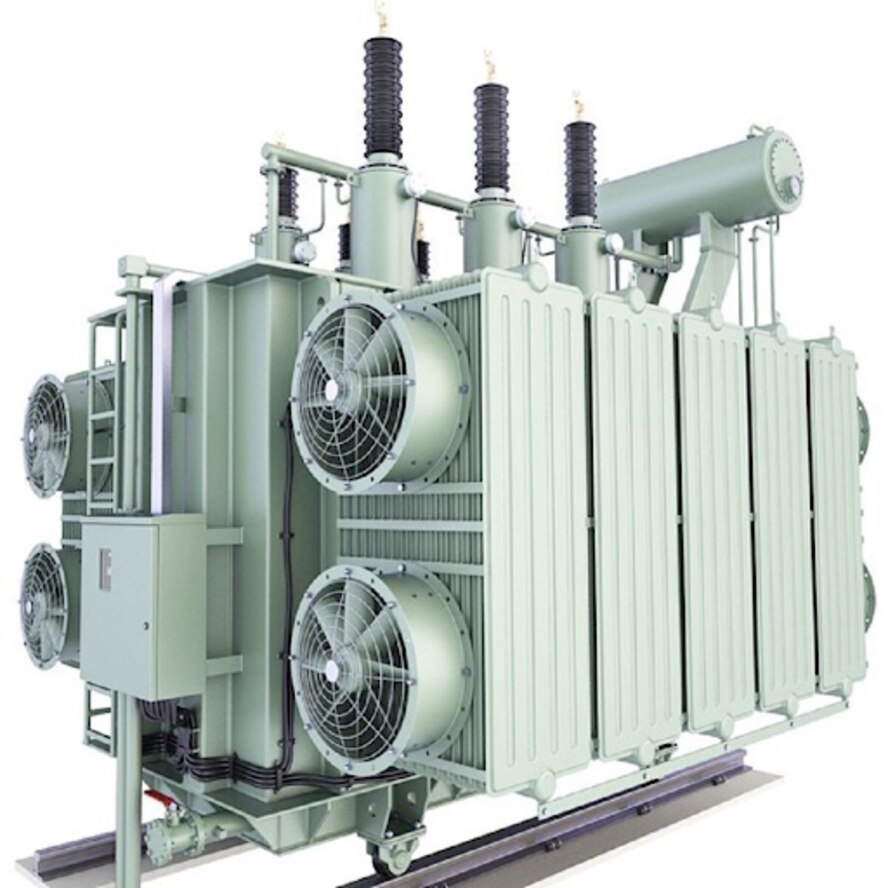
A Kirloskar transformer can show reduced voltage, overheating or repeated trips even when its main windings have not failed. You will be able to identify the likely fault, specify the right diagnostic tests, decide between site repair and workshop overhaul, and verify that the transformer is safe to return to service.
Key takeaways
- Record the transformer’s rating, vector group, tap range and insulation liquid first.
- Use visual checks, oil tests and electrical measurements to locate the fault.
- Choose repair, overhaul or replacement from test results—not the symptom alone.
- Use workshop overhaul when the transformer needs controlled access, drying or major rewinding.
Define the Kirloskar Transformer Before Diagnosing the Fault
The repair scope starts with the transformer’s identity, not its symptom. Record the Kirloskar model or series, serial number, oil-filled transformer or dry-type transformer construction, distribution or power duty, phase arrangement, voltage class, kVA or MVA rating, cooling class, vector group, impedance, tap range and insulation liquid.
1. Collect the nameplate, single-line diagram, winding and terminal drawings, previous test reports, oil analysis and maintenance history. Confirm whether the unit uses an off-circuit or on-load tap changer, conservator, Buchholz relay, radiators, fans or pumps.
A wrong vector group, tap range or connection detail can leave a repaired transformer unusable even when insulation results look satisfactory.
2. Match each symptom to the equipment detail before approving Kirloskar transformer repair. Overheating demands load, ambient, cooling-stage and harmonic history; oil leakage demands inspection of gaskets, radiators, bushings and the conservator; abnormal humming points toward core, mounting or overexcitation concerns. Low insulation resistance demands temperature-corrected results and test configuration, not an arbitrary pass limit.
3. Treat winding imbalance, repeated tripping, dissolved-gas alarms and reduced output voltage as separate clues. Check phase currents, protection settings, tap position and supply voltage before blaming the windings. Bushings require independent attention because capacitance, dissipation factor, terminal connections or bushing oil can fail while main-tank oil appears acceptable.
Give the repairer a defined scope, including the actual alarm and trip path, fan or pump controls and remote indications. A distribution transformer repairer in Mumbai should receive these records before recommending parts, oil treatment, workshop dismantling or replacement.
Trace Symptoms Through a Structured Inspection and Test Programme
Trace performance loss by moving from operating evidence to targeted transformer testing. Review load history, relay trips, dissolved-gas alarms and temperature trends before isolating, discharging and earthing the unit. Inspect the tank, conservator, radiators, gaskets, bushings, breather, marshalling box and tap-changer compartment for leaks, contamination, cracks or loose connections.
- Record oil level, winding and ambient temperatures, then sample oil without contaminating the bottle.
- Perform an insulation-resistance test between windings and from windings to earth; record temperature, duration and connected equipment.
- Perform a polarization-index test by comparing the 10-minute insulation resistance with the one-minute value. Compare both results with temperature-corrected historical readings, not an arbitrary universal limit.
- Make a winding-resistance measurement in transformer at the correct tap and common winding temperature. Phase imbalance or abnormal changes across taps point toward contacts, joints or winding damage, not insulation alone.
- Operate the on-load tap changer separately, checking contact resistance, motor speed, position indication, interlocks and control response.
- Function-test Buchholz, sudden-pressure, pressure-relief, temperature, fan, pump, alarm, trip and remote circuits through the actual protection path.
| Test focus | Evidence of loss | Likely area |
|---|---|---|
| Turns-ratio and vector-group tests | Wrong ratio or phase relation | Windings or tap changer |
| Oil breakdown voltage and dissolved-gas analysis | Low dielectric strength or fault gases | Oil or internal insulation |
| SFRA and magnetic-balance tests | Changed response or unequal excitation | Core movement, clamping or windings |
| Bushing capacitance and power-factor tests | High loss or unstable readings | Bushings |
| Control and trip tests | Failed indications, lockouts or alarms | Controls and auxiliaries |
Choose Repair, Overhaul or Replacement From the Evidence
A repair is justified when test results localise the defect and the core, tank and insulation system remain structurally sound. A replacement becomes safer when the core has severe interlaminar damage, the tank is badly corroded, winding insulation is broadly carbonised, or the required parts and design data cannot be verified.
| Defect or finding | Decision | Required work |
|---|---|---|
| Loose connection, localised winding-joint damage | Repair | Transformer winding repair, joint tightening, insulation restoration and resistance checks |
| Degraded oil with sound paper insulation | Repair | Transformer oil filtration, leak correction and oil-quality testing |
| Cracked or electrically deteriorated bushing | Repair | Transformer bushing replacement, terminal inspection and capacitance and dissipation-factor checks |
| Worn or contaminated tap contacts | Overhaul | Tap-changer maintenance, contact inspection, mechanism adjustment and operation checks |
| Severe core movement, extensive arcing or carbonised windings | Replace or specialist rebuild | Compare repair cost, lead time and remaining insulation life against a replacement unit |
A proper overhaul is more than cleaning and changing oil. Record the nameplate, vector group, tap range, impedance, cooling class and insulation-liquid type before opening the unit, then inspect the core, clamping structure, windings, leads, earthing, gaskets and conservator.
Replace damaged seals, correct leaks, clean the tank and verify every connection. After reassembly, establish a baseline with turns-ratio and phase-relation checks, temperature-corrected winding resistance, insulation tests, bushing tests, oil tests, tap-changer operation, grounding and leak inspection. Test Buchholz, pressure-relief, temperature alarm, fan, trip and remote circuits through their actual alarm and trip paths.
A single acceptable megohm reading does not prove the overhaul succeeded.
Compare On-Site Intervention With Workshop Overhaul
Repair at the plant makes sense when the fault is accessible, the tank remains sound, and testing shows that the windings and core do not need factory equipment. Oil filtration, leak sealing, bushing or terminal replacement, control checks and tap-changer adjustments can reduce downtime through on-site transformer repair.
| Option | What it means | When it applies |
|---|---|---|
| On-site intervention | Isolate, earth, test and repair the installed unit with controlled oil handling | Minor leaks, contaminated oil, loose connections, defective accessories or accessible tap-changer faults |
| Transformer workshop overhaul | Drain and open the unit, inspect active parts, dry insulation, repair windings or joints, and rebuild and test it | Winding damage, core faults, severe moisture, internal arcing, major bushing failure or tank damage |
| Replacement or specialist recovery | Compare repair risk with a new or exchange transformer | Fire damage, extensive deformation, obsolete parts or repair cost that approaches replacement value |
Move the unit to a workshop when the repair requires lifting the active part, vacuum drying, winding access, controlled brazing or repeated electrical tests. Transformer lifting and transport then become a risk calculation: confirm route clearance, crane capacity, centre of gravity, oil-drain requirements and protection against shock and moisture.
Gelstar Engineering Services can help coordinate transformer repair and service Kopar Khairane requirements when the scope includes site testing, removal planning and workshop handover. Do not approve transport from an acceptable oil dielectric-breakdown result alone; review dissolved gases, insulation trends, winding resistance by tap and bushing condition first.
Recommission the Transformer and Restore Its Operating Margin
Return to service only after transformer recommissioning proves the repair addressed the original failure mechanism. Do not treat one acceptable insulation-resistance reading as proof. Record tap position, oil temperature, ambient temperature, test instruments and every result against the pre-repair data.
- Verify turns ratio, phase relation, vector group and winding resistance at each tap; investigate any new imbalance.
- Repeat insulation-resistance and polarization-index tests, then compare the readings with the original fault and the manufacturer’s limits.
- Assess each bushing independently with capacitance and dissipation-factor tests; inspect terminals, gaskets, conservator fittings and the tank for leaks.
- Operate the tap changer through its full range and test alarms, lockouts, Buchholz trips, temperature trips, cooling stages and control interlocks.
- Confirm earth continuity, clearances, correct phase identification and satisfactory no-load energisation before applying load.
Take oil samples with clean, compatible equipment using ASTM D923 practice, protecting the sample from air contamination and dissolved-gas loss. Use a traceable laboratory report and a defined panel covering breakdown voltage, moisture, acidity, interfacial tension, dissipation factor, resistivity, inhibitor status, particles and dissolved gases.
Dissolved-gas analysis is a trend, not a pass/fail verdict. Interpret gas concentrations, generation rates, key gases, ratios, loading and operating history through IEC 60599 oil analysis guidance, then establish a post-repair baseline.
Increase load in controlled steps while checking winding hot-spot temperature, cooling availability and harmonics. Use IEC 60076 loading guidance to confirm operating margin; former peak load is not automatically safe after repair.
Frequently asked questions
What information should you record before diagnosing a Kirloskar transformer fault?
Record the model or series, serial number, construction, duty, phase arrangement, voltage class, kVA or MVA rating, cooling class, vector group, impedance, tap range and insulation liquid.
How do you trace a Kirloskar transformer fault systematically?
Start with a visual and operational inspection, then use oil analysis and electrical tests to connect symptoms with insulation, winding, bushing, tap-changer or cooling-system faults.
When should you repair, overhaul or replace a transformer?
Use repair for a defined, localised defect; choose overhaul for major internal work or degraded insulation; consider replacement when damage, age, capacity or repair risk makes restoration uneconomic.
When is workshop overhaul preferable to on-site transformer repair?
Choose workshop overhaul when the transformer needs controlled drying, core and coil access, rewinding, extensive testing or specialist equipment that cannot be safely deployed at site.