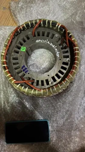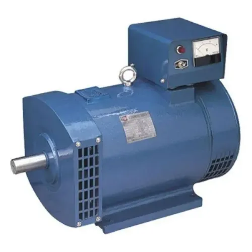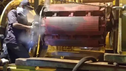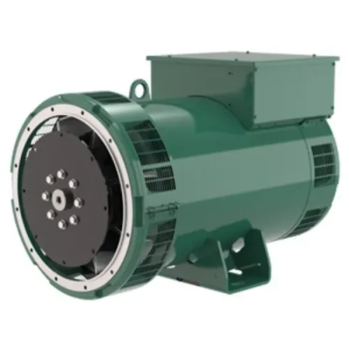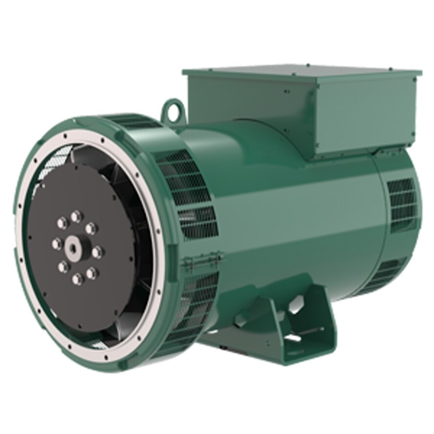
Low voltage, unstable voltage, no output and voltage collapse under load can come from the engine, sensing circuit, AVR, exciter, rotating rectifier, rotor or stator. By separating those fault paths and testing them in the correct order, you can avoid replacing an AVR when the real problem is speed, a diode, a winding, a wiring link or a damaged protection component.
Key takeaways
- Check engine speed and 50 Hz frequency before condemning the AVR.
- Record the alternator model, serial number, AVR type and wiring configuration.
- Separate sensing, winding, excitation and rotating-rectifier faults with measured values.
- Require insulation, winding, voltage and load-test records before returning the machine to service.
Start with speed, frequency and the exact voltage symptom
A 50 Hz alternator speed problem can imitate an AVR failure: if the engine runs below its nameplate speed, terminal frequency falls and the AVR’s UFRO deliberately reduces excitation below its knee frequency.
Measure prime-mover speed and terminal frequency at no load and under load before changing voltage or stability settings; adjustment cannot correct an engine-speed fault.
- Residual-voltage-only output or no output points toward lost excitation build-up, an AVR supply fault or field-circuit interruption.
- Low voltage at no load points toward excitation, sensing or speed; confirm frequency first.
- Normal no-load voltage with poor loaded voltage points toward rotating diodes, exciter capacity, field wiring or a stator fault.
- Unstable voltage or hunting requires checking frequency, sensing connections and the stability setting; excessive stability slows recovery, while insufficient stability causes hunting.
- Voltage collapse during motor starting requires a frequency reading during acceleration before increasing excitation.
- Overvoltage requires an overvoltage diagnosis covering sensing-wire errors, AVR failure and excessive speed.
- Phase-voltage imbalance indicates a sensing, connection or stator problem.
- Blown AVR fuses require isolation and inspection for shorted excitation, wiring or regulator damage.
2. Separate regulation from output loss by comparing every phase voltage and current under load. Balanced voltage with reduced current or kVA suggests an open stator phase, high-resistance joint, damaged connection, wrong phase sequence or protective-device operation—not automatically an AVR fault.
Record the readings before replacing or adjusting anything. A qualified test procedure must use the machine’s specified sensing mode and load.
Identify the Leroy Somer machine and regulator before testing or replacing anything
Do not order an AVR until you record the Leroy Somer alternator model and serial number. Collect the following nameplate data, manual details and control-panel information:
- Rated kVA, rated voltage, frequency, and star or delta connection
- Excitation system, including PMG excitation or self-excitation
- AVR part number and the machine wiring diagram
- Stator-link positions, line-to-line and line-to-neutral ratings
- Frequency-selection links or switches and AVR sensing terminals
R438, R449, D350 AVR and digital regulators cannot be selected by output voltage alone. Their terminal functions, sensing arrangements and excitation-current limits differ; a substitute can produce incorrect excitation or damage the regulator. Compare every link and terminal with the nameplate data wiring diagram before adjustment.
| Excitation arrangement | What to investigate | What not to assume |
|---|---|---|
| Self-excited | Residual magnetism, AVR supply, field circuit and rectifier | Loss of residual magnetism proves AVR failure |
| PMG excitation | PMG output, PMG wiring, rectifier and regulator circuit | Field-flashing will cure a PMG fault |
For live testing, use an approved energized procedure with barriers, rated instruments and competent personnel. For dead testing, isolate, apply lockout tagout, discharge stored energy and confirm zero voltage.
Disconnect or protect the AVR, PMG equipment and electronic accessories as the Leroy-Somer manual specifies; never apply a megohmmeter across connected AVR terminals, PMG equipment or electronic accessories.
Use winding, sensing and excitation measurements to separate the fault paths
Measure from the AVR outward: supply, sensing, excitation, rotor and main stator. Record readings against the Leroy-Somer wiring diagram, not against a guessed terminal number. Perform an insulation resistance test only after disconnecting or protecting the AVR, PMG and auxiliary electronics exactly as the manual specifies; a megohmmeter can destroy connected electronics.
- Check AVR supply voltage, then each sensing voltage. Inspect loose terminals, excessive lead resistance, a broken neutral reference, incorrect links and any missing phase in three-phase sensing.
- Perform a winding resistance comparison phase-to-phase. Unequal readings point toward a stator winding or connection fault; one absolute resistance value cannot prove health.
- Check exciter-field continuity, rotating connections and the AVR field-output response. An AVR command with little or no excitation-field current points toward the regulator, field circuit or wiring.
- Compare exciter and main-field behaviour under controlled load. Normal excitation with unbalanced stator resistance points toward the main stator or its connections.
- Treat a continuity beep only as evidence of a closed circuit. It will not reveal shorted turns, insulation breakdown, high-resistance joints or a winding that fails under load.
| Fault path | Measurement pattern | Likely direction |
|---|---|---|
| AVR or field wiring | Command present, little or no field current | Regulator, supply, wiring or field circuit |
| Sensing circuit | Supply correct, sensing voltage absent or incorrect | Loose lead, broken neutral, wrong link or missing phase |
| Exciter or rotor | AVR output responds, excitation remains abnormal | Exciter winding, rotating connection or rotor circuit |
| Main stator | Excitation normal, phase resistance or loaded output unbalanced | Stator winding or terminal connection |
Test the rotating rectifier and field-flashing circuit without creating a second failure
A rotating diode can pass enough current to produce plausible no-load voltage yet fail when load increases. An open diode reduces rectified field power; a shorted diode distorts it and increases ripple, so terminal voltage falls or collapses as excitation demand rises.
1. Isolate the alternator, lock out the drive, discharge stored energy and follow the Leroy Somer machine procedure. Do not trust a rotating rectifier assembly diode test made in circuit: exciter and field windings can create false readings.
2. Isolate each diode lead or remove the rotating rectifier assembly as permitted. Perform a six-diode bridge forward reverse check with a multimeter diode-test function or approved tester. Each diode must conduct in the forward direction and block in reverse; a continuity beep alone proves nothing.
3. Perform field flashing only after isolating the AVR and voltage-sensing circuit. Confirm the field flashing polarity voltage and battery rating from the manufacturer’s procedure before connecting anything. Applying battery voltage through an active AVR can destroy its power stage, while reversed field polarity can prevent voltage build-up.
4. After a short circuit, load rejection or diode failure, inspect every surge suppressor varistor field-discharge component for cracking, discoloration, short circuit, open connections or damaged wiring. Replacing the AVR alone can leave a protection fault that destroys the replacement. Recheck excitation response under controlled load before returning the alternator to service.
Decide what repair evidence is required before returning the alternator to service
Do not approve an AVR replacement until an alternator load test proves where the fault lies and the readings meet the machine’s voltage recovery acceptance limits.
1. Record controlled no-load and loaded results: frequency, line-to-line voltage, line-to-neutral voltage, each phase current, kVA and excitation response. Apply and remove a defined load, then record voltage recovery during load changes rather than judging stability from a stationary reading.
2. Adjust stability only under the machine-specific procedure and correct sensing mode. Too little stability causes hunting; too much slows transient recovery and can leave a sound alternator unable to meet its voltage recovery acceptance limits.
3. For parallel operation, verify quadrature droop CT polarity, phase and wiring. A reversed CT can create circulating reactive current, unstable kVAr sharing, or drive one machine toward over-excitation or under-excitation.
4. Investigate output faults that correct regulation cannot cure: an open stator phase, high-resistance terminal joint, damaged winding connection, wrong phase sequence or protective-device operation. A kVA loss from a stator phase fault requires phase-current and voltage comparison, not an automatic regulator swap.
5. Require documented fault isolation, winding and diode results, AVR identification, load-test readings and acceptance limits. This evidence supports the AVR replacement decision and distinguishes rewinding, regulator replacement, field repair or site overhaul; Gelstar Engineering Services can provide that record through a qualified contractor.
Related services
Alternators Repair Services -Leroy Somer Alternators Repair Services -Leroy Somer Leroy Somer Alternators Repair Services We offer a superior quality gamut of LS RRA Diodes & LS AVR Electronic Repair Service.We offer these repair... View service → |
Alternators Rewinding & Repairs Alternators Rewinding & Repairs Ours is a noted firm engaged in offering Alternators Rewinding (Upto 2500 KVA). View service → |
Frequently asked questions
Why can low engine speed look like a Leroy Somer AVR failure?
Below the alternator’s nameplate speed, output frequency falls. The AVR’s UFRO function then reduces excitation below its knee frequency, causing low voltage that resembles an AVR fault.
What should you identify before testing or replacing a Leroy Somer AVR?
Record the alternator model, serial number, terminal voltage, frequency, winding connection, AVR part number and wiring configuration before changing settings or components.
How do measurements separate voltage, excitation and output faults?
Compare speed and frequency with terminal voltage, sensing voltage, winding resistance, insulation resistance and excitation readings. The pattern shows whether the fault lies in the engine, sensing circuit, windings, AVR or exciter path.
What evidence should support an alternator repair before service?
Request recorded insulation-resistance results, winding and diode checks, AVR settings, no-load voltage, frequency, load-test results and protection-trip verification.
Related service
Large Alternators Site Overhauling Large Alternators Site Overhauling We offer a site overhauling of large alternators up to 10 mw undertaken. View service → |