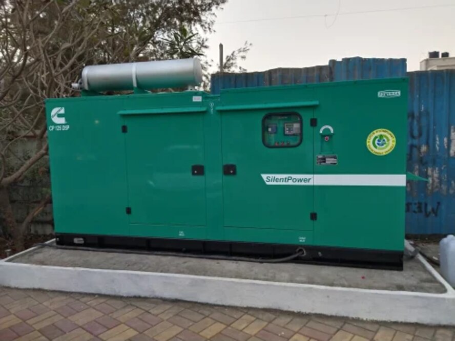
A DG set that fails to start, runs without producing power, or hunts between unstable voltage and frequency needs a staged diagnosis rather than repeated resets or parts replacement. By separating engine, fuel, control, alternator and transfer-equipment faults, you can identify the failed stage and demand test evidence for the repair.
Key takeaways
- Classify the fault as no-crank, crank-but-no-start, or starts-then-stops.
- Trace battery voltage, starter current, interlocks, fuel delivery, and engine-stop signals.
- Check generator output separately from engine operation when the site has no power.
- Record voltage, frequency, load, and shutdown readings instead of accepting “tested OK.”
First classify the failure: no-crank, crank-but-no-start, or starts-then-stops
Classify the DG set starting problem before replacing any part: is it a no-crank DG set, a crank-but-no-start condition, or an engine that starts then stops? Disable remote start, isolate the starting batteries where appropriate, lock out electrical sources, and verify absence of voltage, including backfeed through the automatic-transfer arrangement.
| Symptom | What to check first | What the result means |
|---|---|---|
| No-crank DG set | Measure battery open-circuit voltage and terminal tightness; inspect earth straps, charger output, emergency-stop circuit, controller alarms, starter-solenoid contacts and starter operation. | Low voltage or a large drop during cranking points to the battery, cables or starter. An alarm or open interlock can block cranking without a failed starter. |
| Crank-but-no-start | Confirm crankshaft speed, fuel level and diesel quality; drain water from the fuel bowl, inspect filters, suction-line air leaks, lift-pump delivery, fuel shut-off solenoid, injector operation and fuel or rail pressure. | A turning starter does not prove adequate cranking speed, injection pressure, timing or ECU start permission. Do not condemn injectors before proving fuel reaches them. |
| Starts then stops | Check oil level, coolant level, low-oil-pressure and high-temperature signals, emergency stop, controller fault codes, fuel-return restriction and continued fuel supply. | A protective shutdown can stop a healthy engine. Find and correct the initiating signal or wiring; repeatedly resetting or bypassing protection creates an overspeed, overheating or low-pressure hazard. |
Record battery voltage before and during cranking, start time, fault codes, fuel-pressure evidence and coolant conditions. Check cold-start aids when ambient temperature requires them, then replace a part only after its supply, control signal and mechanical operation fail the test.
Trace the starting circuit from battery voltage to fuel delivery
Start with a meter, not a parts replacement. A starter that turns the engine proves only that the circuit is closing; it does not prove adequate crank speed, fuel pressure, injection timing or start authorization.
1. Measure DG battery voltage at the posts, then measure it at the starter while cranking. A 12 V lead-acid battery commonly must remain near 9.6 V at room temperature; assess a 24 V system against the manufacturer’s limit. Record starter motor voltage drop across the positive cable and earth strap.
Excessive drop identifies loose terminals, damaged cables or a poor ground, even when the battery is charged.
2. Check battery charger output and its alarm status. A charger that is not supplying its specified output leaves the battery weak between attempts. Inspect the starter solenoid contacts and confirm the crankshaft reaches the manufacturer’s required speed.
3. Prove the control permission circuit. Check the emergency-stop circuit, low-oil-pressure or low-coolant alarm, controller fault code and fuel shut-off solenoid. Find the initiating signal; do not repeatedly reset or bypass an interlock.
4. Confirm fuel level and quality, then inspect the water separator and fuel filter blockage. Prime the low-pressure circuit and watch for bubbles or loss of prime, which indicates air entering through a suction hose, filter seal or hand primer. Check lift-pump delivery, injector supply and fuel-return restriction before condemning injectors.
If cranking speed and fuel delivery pass, test injection timing and ECU start-permissive data.
When the engine runs but the site still has no power
A running engine does not prove that the DG set power failure is inside the generator. Before testing, disable remote start, isolate batteries where appropriate, open and lock out electrical sources, verify absence of voltage, and prevent backfeed through the automatic-transfer system.
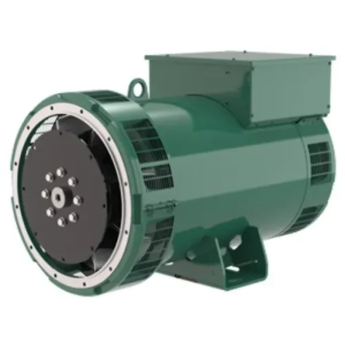
- Measure generator voltage at the alternator terminals, line-to-line and line-to-neutral, with frequency at rated speed. Zero voltage points towards excitation or alternator failure; correct voltage here moves the investigation downstream.
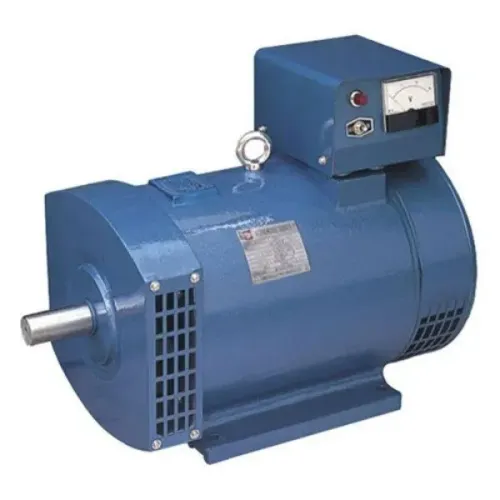
- Check the AVR sensing leads, excitation connections, field fuse, brushes and slip rings. On a slip rings generator, worn brushes or poor ring contact can leave the engine running without usable output. A failed rotating diode can produce low or unstable excitation.
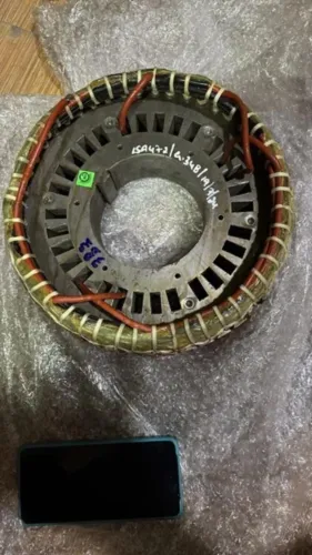
- Test the alternator windings de-energised for continuity, insulation resistance and phase balance. Do not condemn the alternator because a breaker is open.
- Confirm generator-breaker position, trip indications, closing-coil supply, electrical and mechanical interlocks, then inspect phase conductors, neutral and earth connections for an open cable or loose termination.
- At the automatic-transfer switch, test utility and generator sensing voltage, controller alarms, emergency-stop circuits, transfer-coil voltage, mechanical movement and load-side protection. A healthy generator will not energise a site through a failed coil or locked interlock.
A resistive load bank proves basic real-power output but not motor starting, harmonics, neutral current or reactive-power faults. Record voltage, frequency, current, kW, kVA and power factor during defined load steps, then compare generator terminals with the facility load.
Separate unstable frequency from unstable voltage under changing load
A frequency reading that rises and falls with engine speed indicates governor hunting; a steady 50 Hz with wandering voltage indicates an excitation or AVR problem. A four-pole alternator must run at 1,500 rpm for 50 Hz, so confirm speed before changing settings.
| Symptom | What it indicates | Check |
|---|---|---|
| Frequency rises and falls as load changes | Governor hunting, actuator movement, speed-sensor error, fuel restriction or excessive governor gain | Compare engine rpm, frequency and kW during each load step |
| Frequency stays steady but voltage wanders | AVR instability, faulty sensing leads, loose excitation connections or rotating-diode damage | Measure phase-to-phase voltage, sensing voltage and excitation response |
| One phase differs from the others | Phase imbalance, loose terminal, winding fault or uneven single-phase loading | Record all phase voltages and currents; inspect terminals and neutral connections |
| Voltage and frequency collapse together under load | Torque, fuel delivery, droop setting, overload or alternator capacity problem | Apply defined load steps and record current, kW, kVA and power factor |
A generator frequency fluctuation that follows sudden motor starts points toward load-related performance, not an AVR fault. Do not adjust the governor and AVR at the same time; you will lose the evidence showing which control loop failed.
A DG set unstable performance can appear at no load only after warming, or emerge when reactive loads connect. A resistive load bank checks real-power response, but inductive or site-load testing is needed for motor starting, harmonics and reactive-power problems. Record voltage fluctuation separately from frequency at every load step.
Verify the repair with measured results, not “tested OK”
Require the repaired unit to return with a signed DG maintenance report and measured test sheets, not “tested OK.”
1. Record the original complaint, ambient temperature, coolant temperature, battery voltage before and during cranking, start time, controller fault codes, oil level, coolant level, fuel condition, and any bypassed protection. This preserves the evidence instead of hiding a temporary workaround.
2. Show operating readings at no load and at several stable loads: phase-to-phase and phase-to-neutral voltage, frequency, phase current, kW, kVA, and power factor. Include load percentage and duration. A load-bank testing record proves engine response and basic alternator output, but it does not prove transfer-switch operation, motor starting, harmonics, neutral-current behaviour, or reactive-load performance.
3. Demand separate confirmation that the automatic-transfer switch sensed failure, energised its transfer coil, moved the breaker, and completed mechanical and electrical interlocks. Test emergency-stop circuits and load-side protection without leaving a bypass active.
4. Ask for the generator insulation resistance test voltage, duration, winding temperature, corrected result, and polarization index when used. The technician must isolate the AVR, capacitors, surge suppressors, and other electronic equipment first; Gelstar Engineering Services can use this record to distinguish alternator insulation faults from regulator faults.
Return the DG set to automatic operation only after the report identifies the test instruments, calibration status, final alarm status, and the person who authorised handover.
Frequently asked questions
How do you classify a DG set starting problem?
A no-crank fault means the starter does not turn the engine; crank-but-no-start means it turns without firing; starts-then-stops means the engine runs briefly before a shutdown or fuel-control problem stops it.
What should you check when a DG set cranks but does not start?
Trace the starting circuit from battery voltage through the starter, control interlocks, fuel solenoid, fuel filters, injection system, and engine-stop circuit.
Why does a DG set run while the site still has no power?
Check the generator breaker, automatic-transfer switch, protection trips, output terminals, sensing circuits, and backfeed isolation instead of assuming the engine faulted.
How do you distinguish unstable frequency from unstable voltage?
Measure frequency and voltage while applying load: frequency changes point toward engine speed or governor control, while voltage changes point toward excitation, AVR, wiring, or alternator faults.
How should you verify a DG set repair?
Record battery voltage during cranking, start and stop behaviour, no-load and loaded voltage, frequency, protection readings, and performance after the specified load test.